DragonWorx.Bio / Sustainable Building / Sustainable Data Center
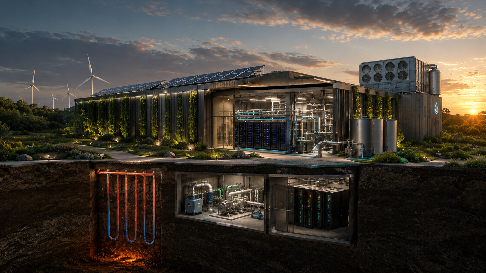
Sustainable Data Center — cross-section cutaway showing geothermal loops, mechanical plant, server halls, solar roof, wind turbines, and native landscaping
DragonWorx.Bio / Sustainable Building / Sustainable Data Center
EXTENDED RESEARCH · CHAPTER 04 OF 09

The Ultimate
Sustainable Data Center

"The most wasteful machine ever built — rethought from the ground down."

Closed-loop cooling Atmospheric water reclaim Geothermal exchange Zero-waste power Biomimetic airflow Net zero operational
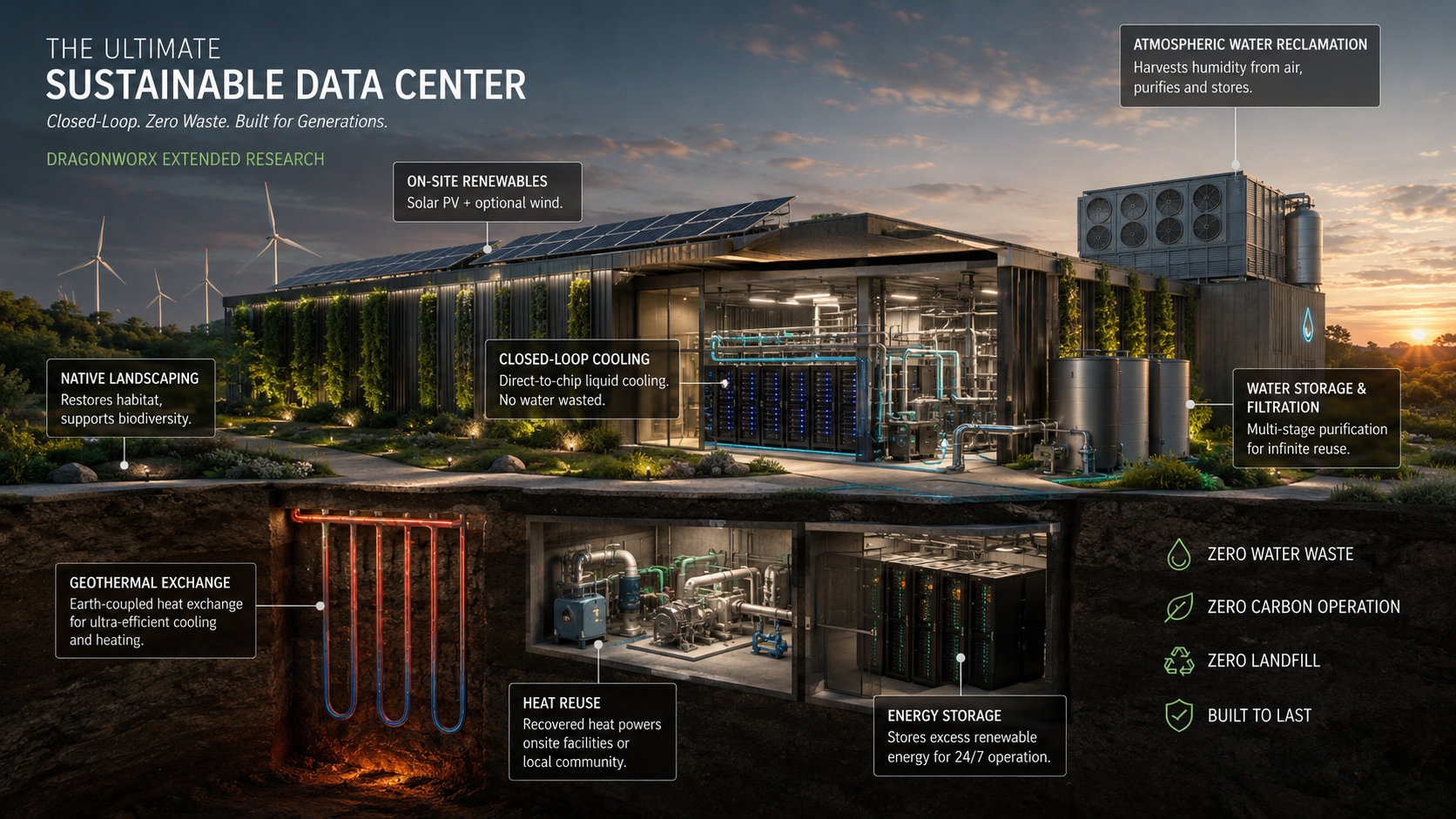
The Ultimate Sustainable Data Center — full composite overview: closed-loop cooling, geothermal, on-site renewables, atmospheric water reclamation

The Ultimate Sustainable Data Center — system composite overview. Click to open full-size. ↗

1.1
PUE target
0
Net freshwater draw
98%
Waste heat recovered
100%
Renewable power
6°C
Ground-loop delta-T
0
Net carbon operational

The data center does not have to be the grid's worst tenant.

The global data center industry consumed approximately 200–250 TWh of electricity in 2022 — roughly 1% of world electricity demand — and that figure compounds each year as AI inference workloads scale. More critically, conventional hyperscale facilities withdraw billions of gallons of fresh municipal water annually for evaporative cooling towers, depositing it into the atmosphere as vapor. They mine cold air from the building envelope and reject thermal waste into a neighborhood that had no say in the arrangement.

The DragonWorx sustainable data center concept starts from a different premise: the building's thermal waste stream, water loop, and power draw are not separate engineering problems — they are one system. Solve the thermal problem correctly and water reclamation becomes a byproduct. Reclaim water correctly and evaporative cooling becomes self-funding. Route waste heat correctly and district energy generation replaces utility dependence. The loops close.

Heat is not waste. It is infrastructure waiting to be routed.

The Problem with Conventional Data Centers

A standard hyperscale facility operates at a Power Usage Effectiveness (PUE) of 1.4–1.6, meaning 40–60% of all electricity drawn goes to cooling rather than computation. Evaporative cooling towers — the dominant cooling method — consume 1–5 gallons of municipal water per kWh of IT load. A 100 MW facility can draw 50–250 million gallons annually. That water leaves the local watershed entirely.

The thermal energy rejected by that same facility — at 30–45°C exhaust temperature — dissipates uselessly into the sky. At scale, this is a district heating resource squandered. The grid connection runs at full rated capacity 24/7 with no load-shifting mechanism. Diesel backup generators sit idle 99.8% of the time, consuming capital and representing latent carbon in reserve.

Site Selection as a Systems Decision

Before any mechanical engineering begins, site selection determines 60% of the sustainability outcome. The ideal site: annual mean air temperature below 15°C for free economizer cooling hours; access to a non-potable water source (treated wastewater, brackish groundwater, industrial gray water) for cooling makeup; proximity to a district heating load (industrial campus, greenhouse complex, municipal heating network) to absorb recovered heat; and bedrock geology suitable for closed-loop ground heat exchange at 100–300 m depth.

Nordic and high-altitude sites achieve economizer cooling for 8,000+ hours annually. Google's Hamina, Finland facility uses seawater directly. Microsoft's Project Natick demonstrated sealed subsea deployment. Neither required a single cooling tower.


Five cooling strategies — deployed in layers.

💧 Liquid Immersion & Direct Liquid Cooling

The highest-density racks — GPU clusters and inference accelerators — require cooling solutions that air cannot deliver at acceptable flow velocities. Single-phase dielectric immersion cooling submerges servers in engineered fluid (3M Novec, Engineered Fluids EC-100) that extracts heat at the chip surface with no fans, no cold plates, no vibration. Thermal resistance drops by 1,200× versus air. PUE for immersion-cooled modules reaches 1.03.

For standard 1U/2U rack servers, rear-door heat exchangers capture 100% of rack exhaust before it enters the room — transforming each rack into a self-contained thermal unit. No raised floor. No hot-aisle/cold-aisle choreography. Coolant water at 40–45°C inlet temperature circulates in a closed loop to the ground heat exchanger array.

🌍 Geothermal / Ground-Source Heat Exchange

Ground temperature at 100–200 m depth stabilizes at 10–14°C across most continental sites, independent of surface climate. A closed-loop borehole array — 200–400 boreholes at 150 m depth, HDPE pipe, grouted — circulates coolant at 8–12°C supply, returning at 14–18°C after absorbing server heat. The delta-T available from the ground loop reduces or eliminates mechanical chiller operation for the majority of the annual load.

The same borehole array, operated in reverse during winter heating seasons, can provide district heat to adjacent facilities — the data center becomes a net thermal asset to its campus rather than a net thermal liability. Stockholm Data Parks has demonstrated this at scale: server waste heat supplies 10% of city district heat.

🐜 Biomimetic Passive Airflow (Termite-Mound Architecture)

For the low-density compute zones and battery storage facilities, the building envelope itself functions as a passive thermal engine. Following the Eastgate Centre (Harare, 1996) principle — documented in the DragonWorx Sustainable Building research — the building section incorporates a central chimney core heated by metabolic load, peripheral cooling channels at the insulated outer wall, and underground intake plenums where incoming air pre-cools against the earth mass.

Computational Fluid Dynamics modeling of the termite mound channel geometry produces convective airflow rates sufficient to maintain 25°C internal temperature when external temperature stays below 35°C — covering 6,000–7,000 hours annually for most mid-latitude sites with no mechanical fan energy.

❄️ Evaporative Cooling — Closed Gray-Water Loop

For peak summer demand when economizer and ground-loop capacity falls short, evaporative cooling provides supplemental capacity — but exclusively on a closed gray-water circuit. No municipal freshwater draw. The makeup water source: atmospheric water generation (AWG) arrays on the roof, condensate recovered from server room dehumidification, and treated process water from the facility's sanitary loop.

Indirect evaporative cooling (IEC) systems — specifically the Maisotsenko cycle — achieve wet-bulb approach temperatures without direct contact between process air and water, preventing legionella risk and reducing blowdown requirements by 70% versus conventional towers.

🌡️ Waste-Heat Cascading

Rather than rejecting heat to atmosphere, the facility operates a thermal cascade: highest-quality heat (55–70°C from immersion cooling hot-fluid circuits) feeds absorption chillers that produce chilled water — eliminating the paradox of burning electricity to make cold. Mid-grade heat (40–55°C) feeds ORC (Organic Rankine Cycle) micro-turbines that recover 8–15% of thermal energy back as electricity. Low-grade heat (30–40°C) distributes to adjacent greenhouse operations, aquaponic facilities, or district heating — turning the data center into a net energy exporter at the campus level.
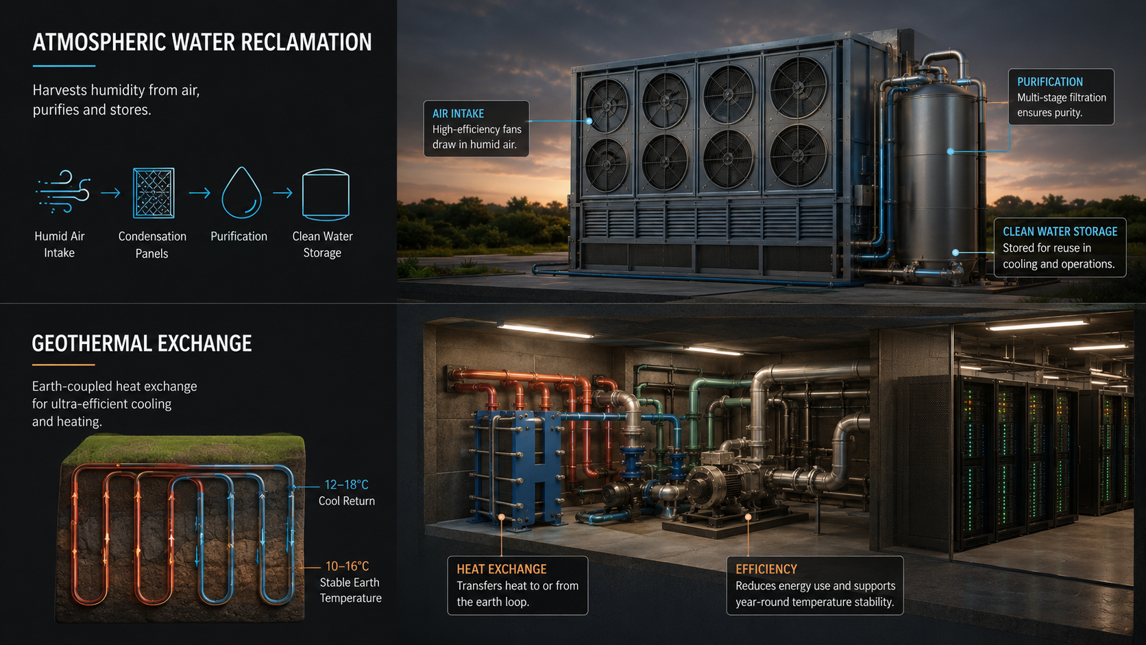
Atmospheric Water Reclamation and Geothermal Exchange systems — AWG condensation unit with multi-stage filtration and closed-loop ground heat exchange pipes, temperature-annotated. GPT-4o render, DragonWorx.
Fig. 4.1 — Atmospheric water reclamation unit and geothermal ground-loop exchange. GPT-4o synthesis from design narrative, May 2026.

Zero net freshwater withdrawal — achieved in three loops.

💧 Atmospheric Water Generation

Fog-net AWG arrays on the building envelope — using hydrophilic polymer netting identical in principle to the Verdant Tower's moisture-harvest facade — collect condensed atmospheric moisture at 20–80 L/m²/day depending on climate. The same superhydrophobic surface chemistry from the DragonWorx materials platform channels collected water to storage cisterns integrated into the building's concrete foundation mass.

In humid climates, AWG alone can supply 30–50% of cooling tower makeup demand. In arid sites, the server room itself becomes an AWG: dehumidification of the data hall, required for equipment reliability, produces 500–2,000 gallons per day of condensate that feeds directly into the cooling water supply — the data center air conditioning is, simultaneously, a water harvesting system.

♻️ Condensate Reclaim & Gray Water Loop

Every liter of water that enters the cooling loop remains in the loop. A side-stream filtration and UV-treatment skid maintains water quality continuously, eliminating blowdown. Biologics are controlled by the same non-chemical photocatalytic treatment used in semiconductor fabs. The cooling tower drift eliminators (if cooling towers run at all) operate at < 0.001% drift loss, recovering vapors that conventional towers release to atmosphere.

Sanitary gray water from the facility (cafeteria, bathrooms, HVAC condensate) routes through constructed wetland treatment beds — using the same biofiltration principle as the Verdant Tower's aquatic biosphere — before entering the cooling makeup supply. Nothing leaves the building water loop except controlled blowdown that meets Class A reclaimed water standards for landscape irrigation.

🌧️ Stormwater as Infrastructure

The facility's green-roof berm — 100% vegetated with native drought-adapted species over a 600 mm growing medium — delays stormwater runoff by 6–8 hours, absorbs 60–80% of annual precipitation on-site, and provides 300 mm of soil thermal mass that buffers the building temperature year-round. Underground cisterns below the green roof store peak-storm overflow for dry-season AWG supplementation. The site produces zero net stormwater runoff in all but 100-year storm events.


A data center that produces power — not just consumes it.

⚡ On-Site Generation Stack

The roof plane carries bifacial BIPV panels across the entire non-mechanical roof area — typically 40–60% of rooftop — generating 800 kW–4 MW depending on facility size. Vertical building faces in suitable orientations carry thin-film PV integrated into the cladding system, reading as surface texture rather than bolted-on hardware. Edge-of-campus open-ground areas host agrivoltaic arrays: dual-use land where PV panels at 3 m elevation shade drought-tolerant food crops below, reducing crop water demand by 30% while generating power above.

ORC turbines on the waste-heat cascade contribute 800 kW–2 MW of baseload generation. The net result: on-site generation covers 25–40% of IT load depending on climate and facility scale — not net-zero by itself, but sufficient to eliminate carbon when paired with a renewable PPA or on-site wind.

🔋 Energy Storage Without Batteries

The facility avoids lithium-ion UPS wherever possible — not for ideological reasons but for lifecycle cost. The primary backup power strategy uses flywheel energy storage (Beacon Power, Amber Kinetics) for the 15-second ride-through required while backup generation spins up, eliminating the chemical battery banks that must be replaced every 5–7 years. For longer-duration storage (hours), the thermal mass of the ground-loop borehole array stores cold overnight and depletes during the day-peak demand window — thermal load shifting without any electrochemical component.

The gravity-regenerative elevator system — identical in principle to the Verdant Tower's kinetic recovery scheme — captures braking energy from freight elevators and server-rack transport systems as a continuous micro-generation source. The contribution is small in absolute terms but eliminates a parasitic load entirely.

⚠️ Eliminating Diesel

Diesel backup generators remain the sustainability Achilles heel of every major data center. The sustainable data center concept replaces diesel with hydrogen fuel cell backup (Bloom Energy, Plug Power): electrolytic hydrogen produced on-site during solar/wind surplus hours, stored as compressed H₂, and fed to PEM fuel cells on demand. Zero combustion. No NOₓ, no particulates, no fuel delivery truck fleet. NFPA 853 compliant for data center applications. Round-trip efficiency (electrolysis + fuel cell) runs 35–45% — worse than a battery, but hydrogen stores indefinitely, making multi-day backup feasible without the chemical degradation constraints of a battery.
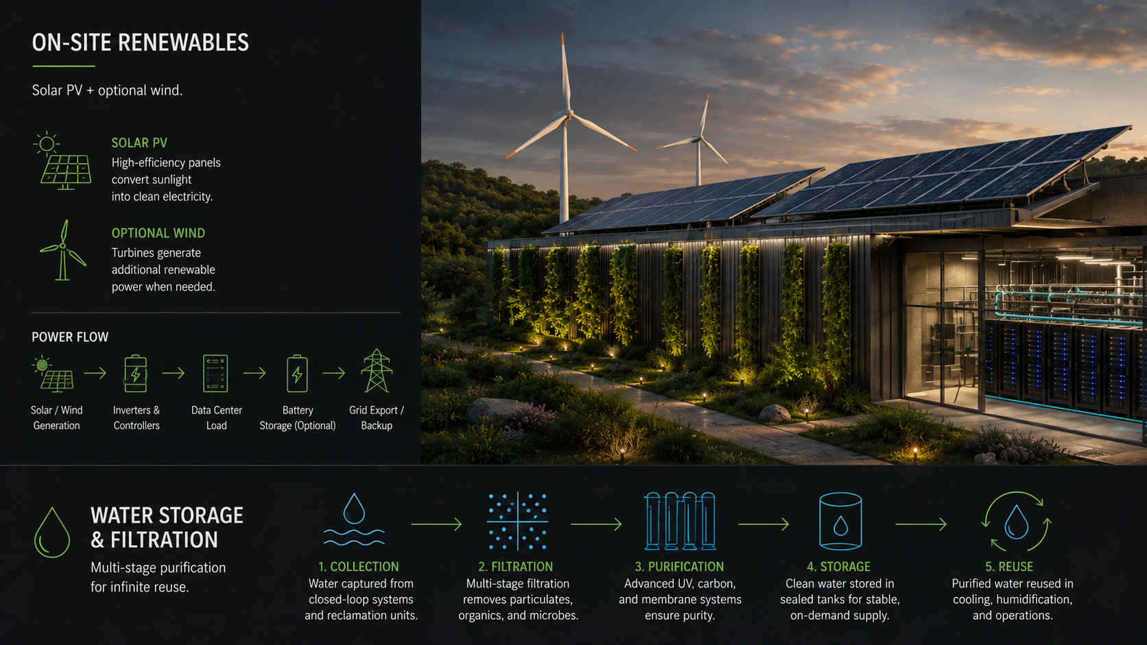
On-site renewables: solar PV and wind turbines with power flow diagram; water storage and filtration five-stage cycle from collection through UV purification to reuse. GPT-4o render, DragonWorx.
Fig. 4.2 — On-site renewables stack and closed water storage/filtration cycle. GPT-4o synthesis from design narrative, May 2026.

The building envelope does the engineering work.

🏗️ Thermal Mass Berm

Both the server hall and the support facilities embed into a sculpted earth berm on three sides, extending 4–6 meters above roof level on the north and east faces. Rammed-earth construction on the berm's outer face provides 2,000 kJ/m³K of thermal capacitance — dampening the daily temperature swing at the envelope by 8–12°C before any mechanical system activates. The berm merges structure with landscape: no separate retaining wall, no separate landscaping contract, no separate stormwater infrastructure.

🌿 Mycelium & Mass Timber Interiors

Non-load-bearing interior partitions — including the cable management infrastructure and rack separation walls — use mycelium composite panels grown from agricultural waste substrate. Fire-rated, zero-VOC, fully biodegradable at end of facility life. Mass timber (CLT) ceiling panels in operations areas replace conventional steel deck, sequestering 25–40 kg CO₂/m² of embodied carbon as a permanent structural store.

🪨 Superhydrophobic Exterior Cladding

Exterior cladding panels carry a lotus-effect superhydrophobic coating — documented in the DragonWorx Sustainable Building research — preventing biological growth (algae, lichen, moss) on the facade without chemical washing. Surface water beads and rolls into collection channels that feed the AWG cistern. Facade maintenance intervals extend from 2–3 years (conventional) to 15–20 years, dramatically reducing embodied carbon and water use over the building's operational life.
Five closed loops. One building metabolism.

Each system feeds the next. The thermal loop provides the heat that drives the ORC turbine that funds the hydrogen electrolyzer. The AWG feeds the cooling loop that reclaims the condensate that returns to AWG storage. Nothing exits the facility that cannot re-enter.

Power Loop

BIPV + agrivoltaic arrays generate daytime surplus. ORC turbines convert waste heat to baseload electricity. Flywheel storage bridges the gap. Hydrogen fuel cells provide multi-day backup without diesel.

💧

Water Loop

AWG fog-net arrays harvest atmospheric moisture. Dehumidification condensate reclaims data hall humidity. Gray water from facility sanitary systems routes through constructed wetland treatment. Zero net municipal draw.

🌡️

Thermal Loop

Immersion cooling extracts chip-level heat at 1,200× better conductance than air. Ground-loop boreholes provide 10–14°C base temperature. Waste heat cascades: absorption chiller → ORC turbine → district heat, in quality order.

🌿

Materials Loop

Mycelium panels grow from agricultural waste and return to soil at end of life. Mass timber sequesters carbon structurally. Superhydrophobic surfaces eliminate chemical maintenance streams entirely.

🌍

Campus Loop

District heat exports feed adjacent greenhouse and aquaponic operations. Agrivoltaic arrays produce food-system outputs from data center footprint. The facility becomes a net contributor to the local energy and food ecosystem.

🌧️

Stormwater Loop

Green-roof berm absorbs 70–80% of annual rainfall on-site. Underground cisterns store peak-storm overflow. Constructed wetland treatment closes the sanitary gray water circuit. Zero net runoff to municipal storm drain.

DESIGN PRINCIPLES

Four ideas the data center refuses to compromise.

01

The Thermal Cascade

Heat leaves the server at the highest possible temperature gradient, and gets extracted at each successive quality level before any residual energy rejects to atmosphere. Rejection to sky represents system failure, not steady-state operation.

02

The Closed Water Loop

Municipal freshwater draw is zero by design — not by offset. AWG, condensate reclaim, and gray water treatment replace utility supply entirely. The facility adds water to the local watershed (via constructed wetland discharge) rather than extracting it.

03

The Productive Envelope

The building skin generates power, harvests water, and moderates temperature simultaneously. No surface functions as mere weather barrier. The berm provides thermal mass, stormwater management, and structural load path in a single material gesture.

03.5

Campus Metabolism

The data center does not optimize in isolation. It couples thermally, hydrologically, and energetically to adjacent land uses — becoming infrastructure for greenhouse agriculture, district heating, and local grid stabilization rather than a standalone energy sink.

Facility Specifications
Facility typeHyperscale / colocation hybrid, 10–100 MW IT load
PUE target1.05–1.15 (industry average: 1.58)
WUE target0.0 L/kWh net (industry average: 1.8 L/kWh)
Primary coolingImmersion + direct liquid, ground-source loop
Secondary coolingBiomimetic passive chimney (termite geometry)
Tertiary coolingClosed gray-water indirect evaporative (Maisotsenko)
Water supplyAWG fog-net + dehumidification condensate + gray water loop
Primary generationBifacial BIPV + agrivoltaic arrays
Secondary generationORC waste-heat turbines
Energy storageFlywheel (ride-through) + thermal mass (load shift)
Backup powerOn-site hydrogen fuel cell (no diesel)
Structural systemConcrete core, rammed-earth berm, mass timber (CLT) interior
EnvelopeSuperhydrophobic lotus-effect cladding, green-roof berm
Interior materialsMycelium composite panels, mass timber ceilings, zero-VOC finishes
Waste heat outputDistrict heat network (campus greenhouse / aquaponics)
Carbon targetNet zero operational; net negative scope 3 via sequestration
Site footprint20–80 acres including agrivoltaic and berm campus
Key Precedents & Proven Technologies
Eastgate Centre, Harare (1996)Termite-mound passive cooling. 10% energy use vs. conventional air-conditioned building. Architect: Mick Pearce.
Google Hamina, FinlandDirect seawater cooling. PUE 1.10. Zero cooling tower, zero freshwater draw.
Microsoft Project NatickSealed subsea deployment. No HVAC, no cooling tower, no human entry. Failure rate 1/8 of land-based equivalents.
Stockholm Data ParksServer waste heat supplies 10% of city district heating. 24 GWh/year recovered thermal energy.
Switch SuperNAP (TAHOE RENO)Achieves 1.18 PUE with hot-aisle containment and outside air economization in high-altitude dry climate.
Bloom Energy (fuel cells)NFPA 853-compliant stationary fuel cells replacing diesel backup at data centers. Zero combustion, grid-independent.
Beacon Power flywheels15-second ride-through at full facility load, 100,000+ cycle life, no chemical degradation.
Maisotsenko-cycle IECIndirect evaporative cooling at 10–20% of conventional chiller energy. Wet-bulb approach without water contact.
DragonWorx Technology Overlap
Auxetic composite panels→ Thermal channel wall geometry (termite-mound passive airflow)
Superhydrophobic surface (AquaSuit)→ Lotus-effect facade cladding + fog-net AWG condensation surface
Helicoidal CFRP joints→ Seismic-resistant berm structure connections
SMP adaptive elements→ Motorless passive damper vanes in chimney channels
Verdant Tower fog-net mesh→ AWG facade panels, identical hydrophilic polymer geometry
Verdant Tower gravity-regen elevator→ Freight elevator kinetic recovery in data center loading bays

Schematic design set — six views.

Pseudo-CAD architectural blueprint renderings synthesized from the DragonWorx design narrative. Each drawing covers a distinct system or view of the facility.

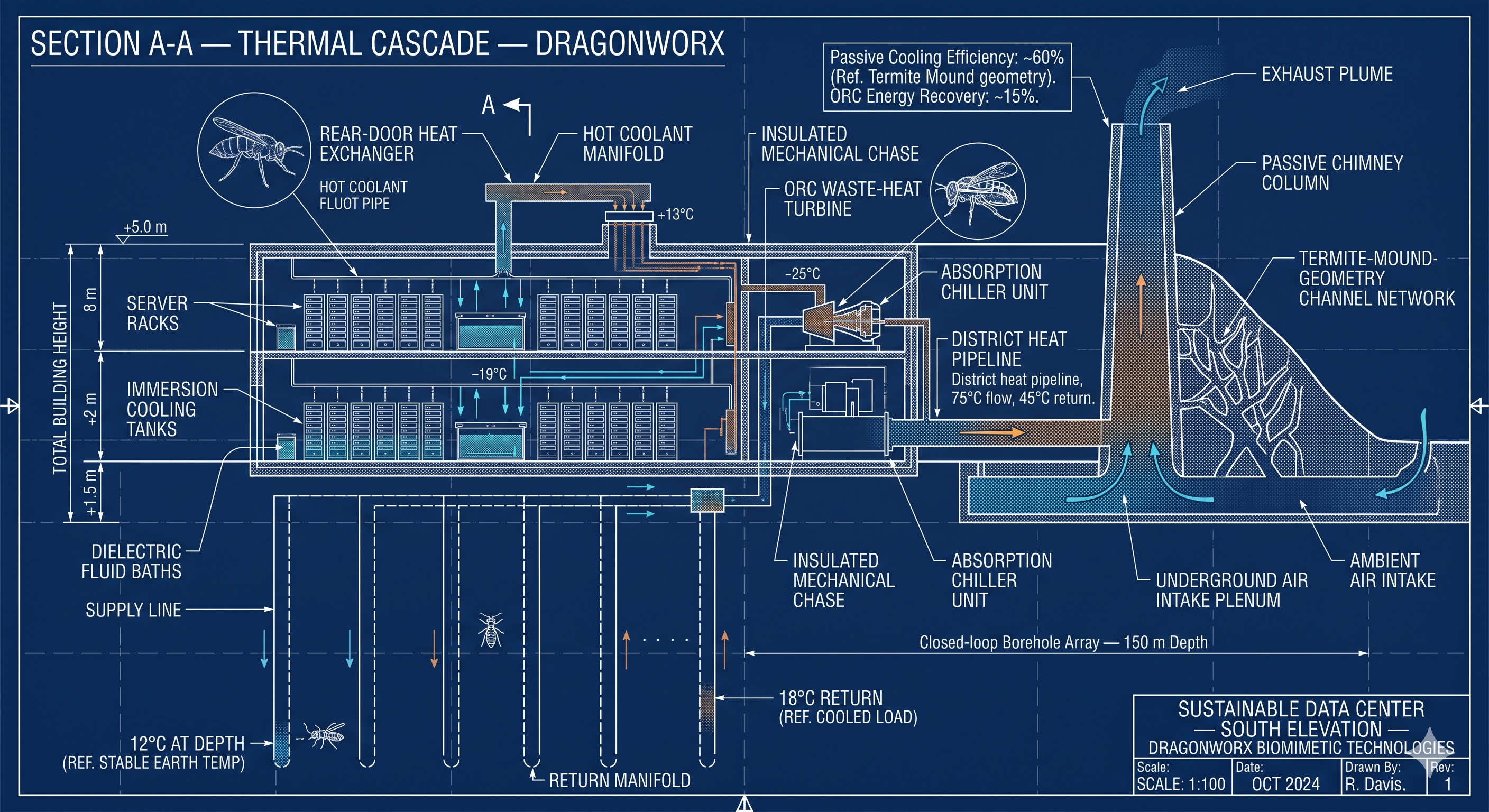
Section A-A — Thermal Cascade — DragonWorx Sustainable Data Center Section A-A — Thermal Cascade longitudinal cross-section: server racks, immersion cooling tanks, ORC waste-heat turbine, absorption chiller, passive chimney column with termite-mound channel geometry, underground borehole array at 150m depth annotated 12°C supply / 18°C return. DragonWorx blueprint.
Fig. 4.3 Section A-A — Thermal Cascade Longitudinal section through the data hall showing the full thermal cascade: immersion cooling tanks → rear-door heat exchangers → hot coolant manifold → ORC waste-heat turbine → absorption chiller → district heat pipeline. Right zone: passive chimney column with termite-mound channel geometry driving convective airflow. Below grade: closed-loop borehole array descending 150 m, annotated 12°C supply / 18°C return. Temperature gradient overlays in amber/cyan.
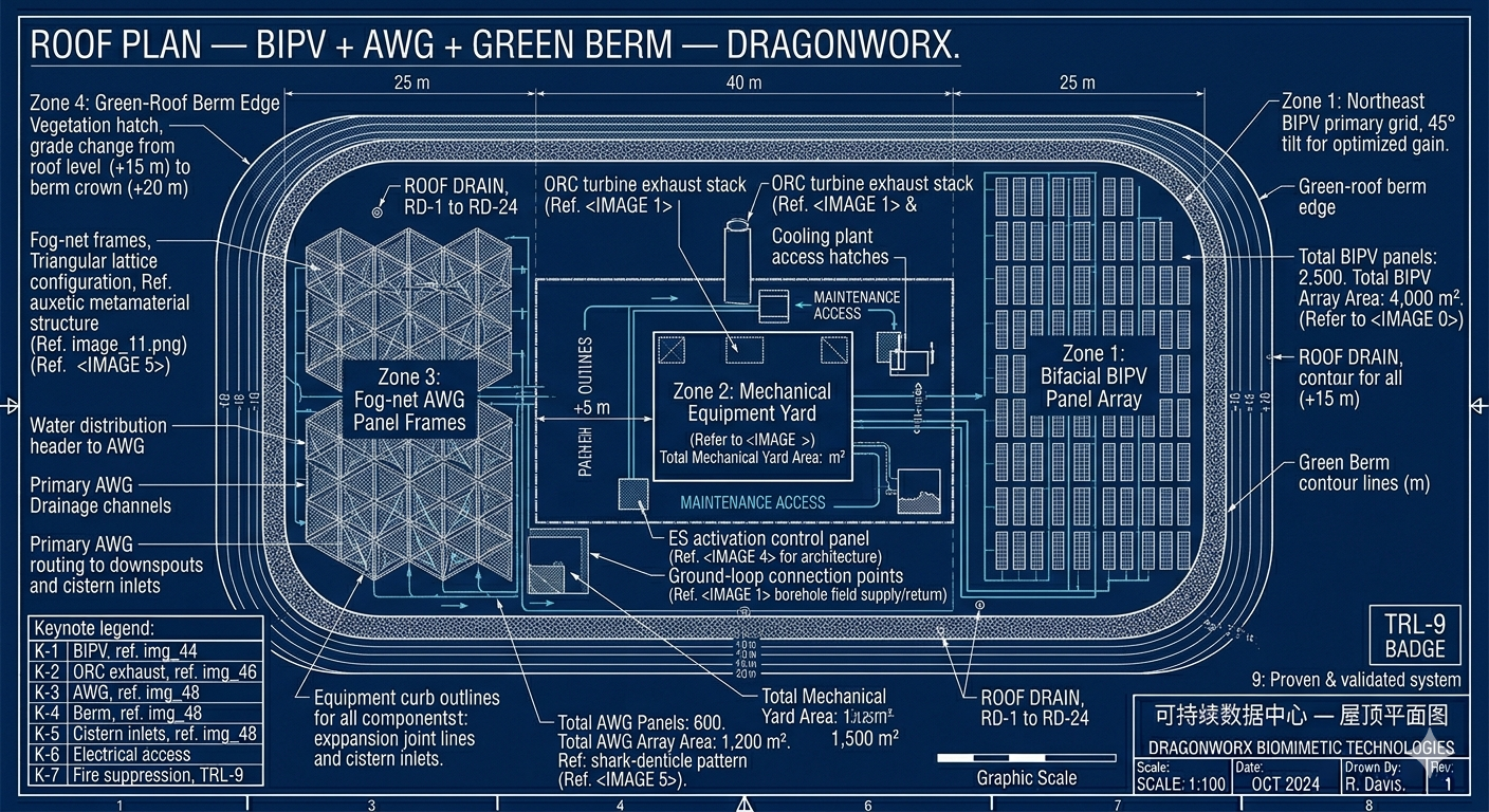
Roof Plan — BIPV + AWG + Green Berm — DragonWorx Sustainable Data Center: Zone 1 bifacial BIPV array northeast, Zone 2 mechanical equipment yard with ORC exhaust stacks, Zone 3 fog-net AWG panel frames in triangular lattice, Zone 4 green-roof berm perimeter with contour lines.
Fig. 4.4 Roof Plan — BIPV + AWG + Green Berm Top-down plan showing the four roof zones: northeast bifacial BIPV grid (2,500 panels, 4,000 m²); central mechanical yard with ORC turbine exhaust stacks and cooling plant access hatches; southwest fog-net AWG panel frames in triangular lattice configuration with drainage channels; perimeter green-roof berm with contour lines grading from +15 m roof level to +20 m berm crown. Keynote legend, roof drain locations, and expansion joint lines annotated.
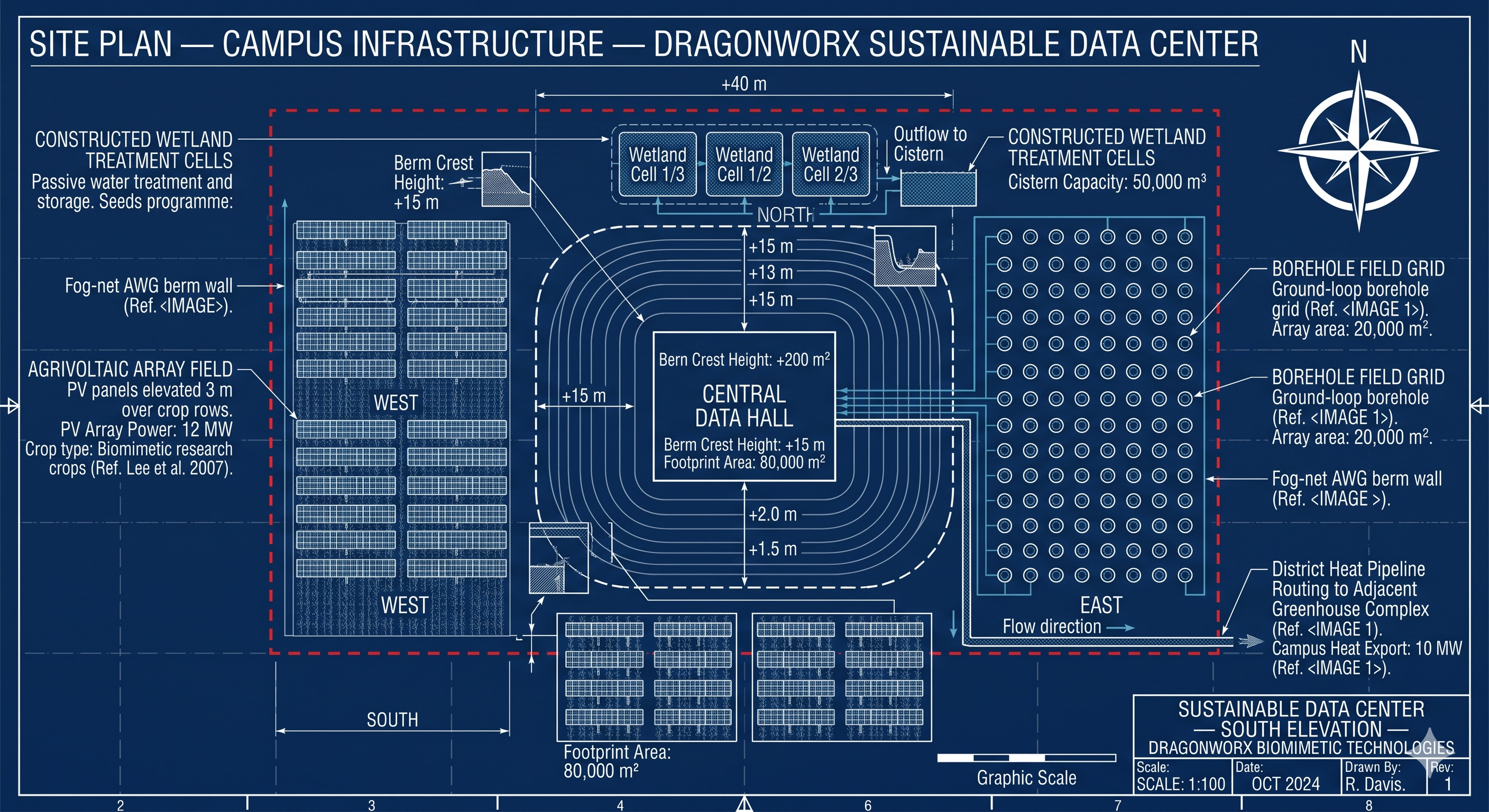
Site Plan — Campus Infrastructure — DragonWorx Sustainable Data Center: central data hall with earth berm contours, west agrivoltaic array field, east borehole field grid, north constructed wetland treatment cells, district heat pipeline routing south to greenhouse complex.
Fig. 4.5 Site Plan — Campus Infrastructure Overhead campus plan across 40+ acres. Central data hall footprint with green-roof berm shown as concentric contour lines at 2 m intervals. West field: agrivoltaic array at 3 m elevation over biomimetic research crop rows, 12 MW PV output. East field: 200-borehole ground-loop array in 10×20 grid at 10 m centres, 20,000 m² array area. North edge: three constructed wetland treatment cells with cistern outflow. Site perimeter: fog-net AWG berm wall (dashed). District heat pipeline exits east to adjacent greenhouse complex, annotated 10 MW campus heat export.
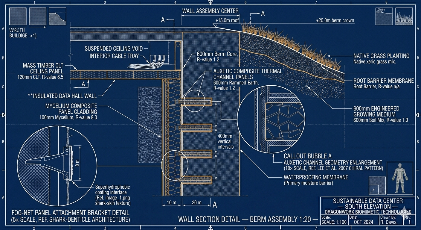
Wall Section Detail — Berm Assembly 1:20 — DragonWorx: interior mass timber CLT ceiling, mycelium composite panel cladding, auxetic composite thermal channel panels at 400mm intervals embedded in rammed-earth berm core, waterproofing membrane, 600mm engineered growing medium, root barrier, native grass planting. Fog-net panel attachment bracket detail callout.
Fig. 4.6 Wall Section Detail — Berm Assembly 1:20 Large-scale wall section from interior data hall to exterior berm crown. Interior: 120 mm mass timber CLT ceiling panel (R-6.5), suspended ceiling cable tray void. Wall: 100 mm mycelium composite panel (R-8.0) on insulated data hall wall. Berm core: 600 mm rammed-earth with auxetic composite thermal channel panels at 400 mm vertical intervals (chiral geometry detail in callout bubble). Exterior: waterproofing membrane, 600 mm engineered growing medium, root barrier, native xeric grass mix. Fog-net panel attachment bracket detail at 5× scale in lower-left callout references shark-denticle surface architecture.
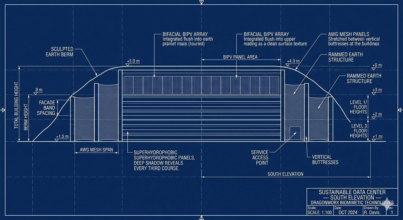
South Elevation — DragonWorx Sustainable Data Center: low-profile three-story building mass emerging from sculpted earth berm, bifacial BIPV array flush in upper facade, horizontal superhydrophobic band reveals, AWG fog-net mesh panels between vertical buttresses, rammed-earth flanks.
Fig. 4.7 South Elevation — Primary Facade Front elevation of the primary facade. Three-story building mass merges into sculpted earth berm rising 5 m above roofline on flanks. South face: bifacial BIPV array integrated flush into upper cladding zone, reading as surface texture. Mid-facade: horizontal superhydrophobic panel system with deep shadow reveals every third course. Flanking buttresses: AWG fog-net mesh panels stretched between vertical elements and tied to downspout collection channels. Rammed-earth berm visible grading away at both sides. Service access point at grade centre-right. Dimension callouts and material keynotes annotated.
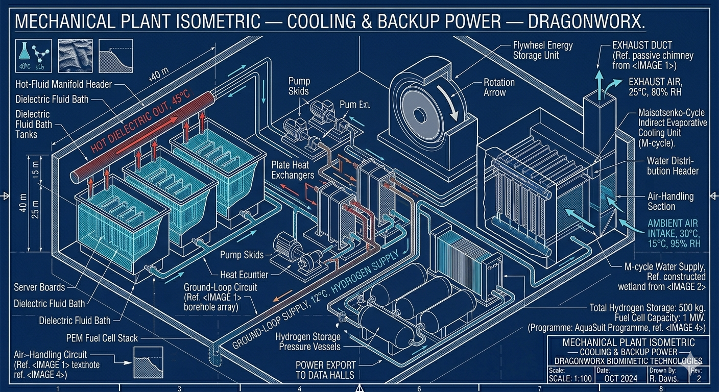
Mechanical Plant Isometric — Cooling and Backup Power — DragonWorx: dielectric fluid bath tanks with server boards, hot-fluid manifold header at 45°C, plate heat exchangers, ground-loop circuit pump skids, Maisotsenko-cycle indirect evaporative cooling unit, flywheel energy storage drum, hydrogen pressure vessels, PEM fuel cell stack.
Fig. 4.8 Mechanical Plant Isometric — Cooling & Backup Power Axonometric cutaway of the mechanical plant room. Left zone: two dielectric fluid bath immersion tanks with server boards submerged, hot dielectric manifold header exiting at 45°C, blue coolant return arrows. Centre zone: plate heat exchangers transferring to ground-loop circuit at 12°C supply; pump skids with flow-direction arrows; heat equaliser linking to ground-loop return at 18°C. Right zone: Maisotsenko-cycle indirect evaporative cooling unit — air-handling section, water distribution header, exhaust duct at 25°C / 80% RH. Background: flywheel energy storage drum with rotation arrow. Floor: compressed hydrogen pressure vessels (500 kg storage) and PEM fuel cell stack (1 MW capacity) with power export line to data halls.

EXTENDED RESEARCH

Interested in the Sustainable Data Center concept?

This project sits within DragonWorx's extended research program — applying biomimetic and closed-loop systems methodology to high-density compute infrastructure.

getdragons@dragonworx.bio All Projects →